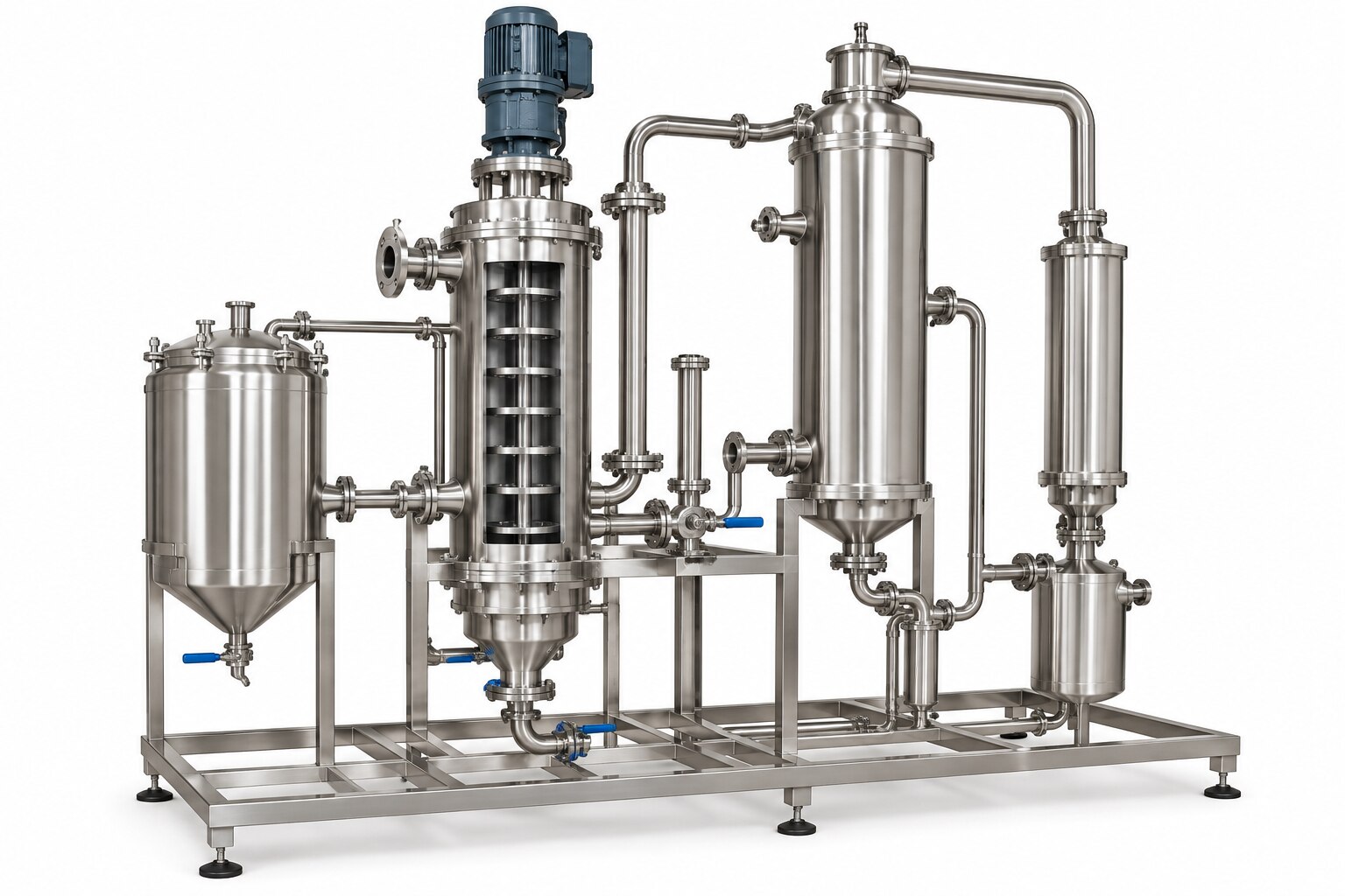
A monsoon-season drop in ATFD evaporation rate does not prove that the heat exchanger is fouled. By separating humidity, rainwater ingress, wet steam, vacuum leakage, cooling-water changes, feed variation and electrical faults, you can identify the actual failure and judge whether a pilot trial produced usable heat-transfer data.
Key takeaways
- Check steam dryness, condenser vacuum and electrical stability before blaming fouling.
- Compare heat-transfer area, surface finish and cleanability against the trial slurry.
- Log pressures, temperatures, flow rates, vacuum and power at fixed intervals.
- Require supplier test records, material certificates, drawings and cleaning procedures.
Map the Vadodara monsoon faults before blaming the exchanger
Rain, humidity and unstable utilities can cut ATFD output without fouling the heating surface. For an ATFD pilot plant for heat exchanger problems during monsoon in Vadodara, map the heat-transfer, vacuum and electrical environment together; otherwise an apparent exchanger failure may be a wet-steam, condenser or control fault.
Track these signals before opening the exchanger:
- Wet steam or poor condensate drainage: lower steam-side temperature, rising condensate temperature, unstable pressure and a widening temperature approach.
- Rainwater or humid feed dilution: higher feed moisture, higher evaporated-water duty, lower outlet solids and wetter powder or cake at the same steam rate.
- Cooling-water warming, reduced flow or air ingress: higher condenser outlet temperature, weaker vacuum and falling evaporation rate while exchanger temperatures remain normal.
- Panel moisture, flooding or voltage dips: erratic sensor readings, interrupted rotor speed, fluctuating vacuum and uneven crust discharge rather than a steady heat-transfer decline.
| Condition | Product signature | Process-data signature |
|---|---|---|
| High humidity or wet feed | Wet cake, softer crust, lower solids | Feed moisture rises; mass balance shows increased water duty |
| Wet steam or blocked condensate path | Unstable powder moisture and intermittent discharge | Steam pressure swings; condensate temperature and exchanger differential pressure rise |
| Warm or fouled condenser | Slower evaporation, possible sticky discharge | Absolute pressure rises with cooling-water inlet temperature; non-condensable load increases |
| Electrical instability or rain ingress | Irregular rotor wiping and crust break-up | Motor current, thermic-fluid temperatures or instruments jump during voltage events |
Treat these as ATFD pilot plant monsoon issues until verified. Compare actual feed and product flows, laboratory moisture, steam or thermic-fluid temperatures, condensate removal and vacuum trends before blaming the exchanger.
Use a diagnostic sequence that separates heat transfer from process faults
Begin with a mass balance and instrument check; opening the exchanger first is how pilot plant heat transfer problems become expensive misdiagnoses.
1. Confirm the feed mass, product mass, distillate rate and steam-condensate rate over the same time interval. Check the load cell for moisture, the pressure transmitter for unstable readings, thermocouples against a reference, and control-panel condensation or loose cable glands. A false feed or vacuum signal is not heat-exchanger failure.
2. Hold feed solids, temperature, viscosity and flow constant, then record agitator current or torque. A rising torque with unchanged steam conditions points to feed thickening, crust formation or rotor overload; it does not prove fouling.
3. Check steam pressure, temperature and dryness, or thermic-fluid inlet and outlet temperatures. Verify steam-trap operation, condensate drainage, exchanger differential pressure and temperature approach. A genuine exchanger fault persists with stable utilities and produces falling duty after you normalize for boiling-point elevation, effective area and driving force.
4. Separate vapour-line restriction from condenser loss by trending ATFD absolute pressure, vapour-line pressure drop, cooling-water inlet temperature and flow, condenser outlet temperature, and non-condensable load together. A rising line drop suggests blockage; rising cooling-water temperature or poor flow with a clean line indicates condenser loss.
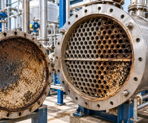
5. Only then isolate and inspect the exchanger for deposits, wet insulation, corrosion at supports and low points, or damaged surfaces. These checks target heat exchanger problems during monsoon without confusing rain-season utility faults with fouling.
Compare the exchanger surfaces used in an ATFD pilot plant
A thin, low-viscosity feed can make any surface look adequate; concentrated, scaling liquor exposes the choice. For ATFD pilot testing in Vadodara, compare normalized duty using boiling-point elevation, effective area, evaporated-water rate and fouling time.
| Surface | Viscosity response | Scaling response | Rotor or pump load |
|---|---|---|---|
| Jacketed wall | Heat transfer falls as viscosity thickens the boundary layer; the flow path stays simple. | Wall deposits narrow area and create hot spots; cleaning is straightforward. | Rotor load rises indirectly through crust and wiping resistance. |
| Internal coils | Adds area, but viscous liquor can bypass or stagnate around tubes. | Coil gaps trap crystals and complicate cleaning. | Rotor clearance and torque become critical; contact can damage both surfaces. |
| External circulation exchanger | Pumped flow keeps the rotor zone open; pump power rises with viscosity. | High velocity delays deposits, but bends, channels and returns can plug. | Rotor load stays lower; pump differential pressure becomes the warning. |
| Scraped or agitated surface | Renews a viscous film at the wall. | Scrapers remove developing scale, but abrasive crystals accelerate wear. | Torque rises directly with viscosity, solids and clearance loss; trip protection matters. |
Pilot performance does not scale linearly: geometry changes wiping frequency, film distribution, residence time and area-to-throughput ratio. Log torque, viscosity, solids, differential pressure, steam pressure and temperature, condensate removal, evaporated-water rate and fouling time; humidity itself does not lower clean heat transfer.
Record the numbers that make a monsoon trial defensible
Set acceptance limits before atfd pilot testing in vadodara, then record values at five-minute intervals. A defensible run proves that heat duty, vacuum and product concentration remain stable together; a brief increase in evaporation rate proves very little.
| Measurement | Stable result | Failure signal |
|---|---|---|
| Steam or thermic-fluid inlet temperature and pressure | Variation within ±3% for 60 minutes | Falling duty despite constant feed |
| Boiling temperature, corrected for boiling-point elevation | Within ±2°C of the recorded setpoint | Apparent heat-transfer gain from incorrect pure-water data |
| Evaporated-water rate and feed/product mass balance | Mass-balance closure within ±5% | Product rate masking feed fluctuation |
| Overall heat-transfer coefficient, U | End value no more than 15% below clean-start value | Progressive fouling |
| Vacuum, vapour-line differential pressure and condensate subcooling | Each remains within ±5% of its steady value | Air ingress, blocked vapour path or poor condensate removal |
| Feed conductivity, total dissolved solids, pH and viscosity | Each changes within pre-agreed operating bands | Process-load change misidentified as fouling |
Calculate U from measured duty, effective area and a stated logarithmic temperature difference. Include condensate subcooling and the concentrated-liquor boiling temperature; otherwise pilot plant heat transfer problems can be hidden by an overstated temperature driving force.
Hold steady operation for at least 8 hours after stabilisation, or for three complete feed-residence periods when longer. Report clean-start and end-of-run values separately, then inspect the surface and record deposit thickness, coverage and cleaning effort. A stable outlet concentration alone is not acceptance.
Prepare the pilot plant and specify the evidence you need from a supplier
Inspect the exchanger, supports, drain points, flange crevices, insulation terminations and stainless-steel/carbon-steel interfaces before rain arrives. Protect low points from standing water, repair cladding, seal cable glands, provide panel drainage and anti-condensation heating, and secure earthing. An IP rating alone will not prevent condensation inside a control panel.
1. Record a dry-weather baseline: steam pressure and temperature, condensate temperature and flow, thermic-fluid inlet and outlet temperatures, absolute pressure, feed rate, boiling temperature, boiling-point elevation, evaporated-water rate, agitator load, exchanger differential pressure and temperature approach.
2. Trend cooling-water inlet temperature, flow, condenser outlet temperature, absolute pressure and non-condensable load together. This separates seasonal condenser loss, air ingress or poor venting from exchanger fouling.
3. Photograph insulation damage, corrosion stains, wet panels, drain paths and deposits. Save calibration certificates, alarm history, mass-balance calculations, cleaning records and a time-stamped trend file. Name the trial record ATFD pilot plant for heat exchanger problems monsoon in Vadodara.
4. Ask the supplier for a P&ID, heat-duty calculation using actual area and a stated temperature-driving-force method, fouling allowance, pressure-drop limit, materials list, inspection plan and acceptance test. Chemie Processors can support a useful decision by tying the proposed surface and utilities to your measured feed viscosity, scaling rate, vacuum and monsoon protection requirements.
Treat ATFD pilot plant monsoon issues as combined heat-transfer, vacuum and electrical risks, not proof of fouling.
Related products
 | ₹750000 Product Details: Capacity(kg) 150 Automation Grade Automatic Usage/Application Industrial Material Stainless Steel Power Source Steam / Thermic Fluid... View product → |
 | ₹749999 Product Details: Capacity(kg) 150 Material Stainless Steel Power Source Steam / Thermic Fluid / Electric Usage/Application Industrial Country of... View product → |
Frequently asked questions
Which monsoon conditions can reduce ATFD pilot plant performance in Vadodara?
Wet steam, unstable cooling water, condenser limitations, vacuum leaks, high humidity and electrical fluctuations can reduce output without exchanger fouling. Map these conditions alongside feed, steam and condensate data.
How do you separate heat exchanger faults from other ATFD process faults?
Use a fixed diagnostic sequence: verify feed properties and flow, check steam pressure and condensate removal, test vacuum and condenser performance, inspect electrical stability, then assess heat-transfer resistance and fouling.
Which heat exchanger surfaces should you compare in an ATFD pilot plant?
Compare surface material, geometry, heat-transfer area, surface finish, fouling resistance, cleanability and compatibility with the slurry. The best choice depends on solids loading, viscosity, corrosion risk and cleaning method.
What data makes an ATFD monsoon trial defensible?
Record feed and concentrate flow, solids, temperatures, pressures, steam quality, condensate rate, vacuum, cooling-water conditions, motor load, power interruptions and cleaning events with timestamps.
Keywords